
PID Controller: Types, Working and its Application
- 2024-04-13
Knowledge is power. And in today’s world, it is the key to opening doors of opportunity and advancement. In this article, learn more about the structure and working of a PID controller. PID controllers have a wide range of applications in industrial processes for process control. 95% of the closed-loop operations of the industrial automation sector use PID controllers. Hence being in the know about PID controllers is of the essence.
What is a PID controller?
Before getting into its nitty-gritties, let’s first understand what a PID controller really is. PID full form in electrical and electronics is a Proportional-Integral-Derivative controller. The definition of a PID controller is that it is a control loop mechanism that “continuously calculates an error value e(t) as the difference between a desired setpoint (SP) and a measured process variable (PV) and applies a correction based on proportional, integral and derivative terms (denoted P, I, D respectively), hence the name.”
In other words, it is a versatile feedback compensator structure used to regulate temperature, flow, pressure, speed and other process variables. It is easily understandable, quite practical and the most accurate and stable controller. What makes it a simple yet sophisticated device is that it is fundamentally easy enough for any engineer to understand as the root concepts are differentiation and integration but it also performs the complex tasks of capturing the behavior of a system and predicting its future behavior.
Working principle
The working principle of a PID controller is that the proportional, integral and derivative terms can be adjusted or “tuned” separately. Based on the difference between these values, a correction factor is calculated and applied to the input. This is done to get the values to meet the current requirement. The work can be broken down into three steps:
PID controller block diagram
Here is the block diagram of a PID controller to help you visualize the working principle.
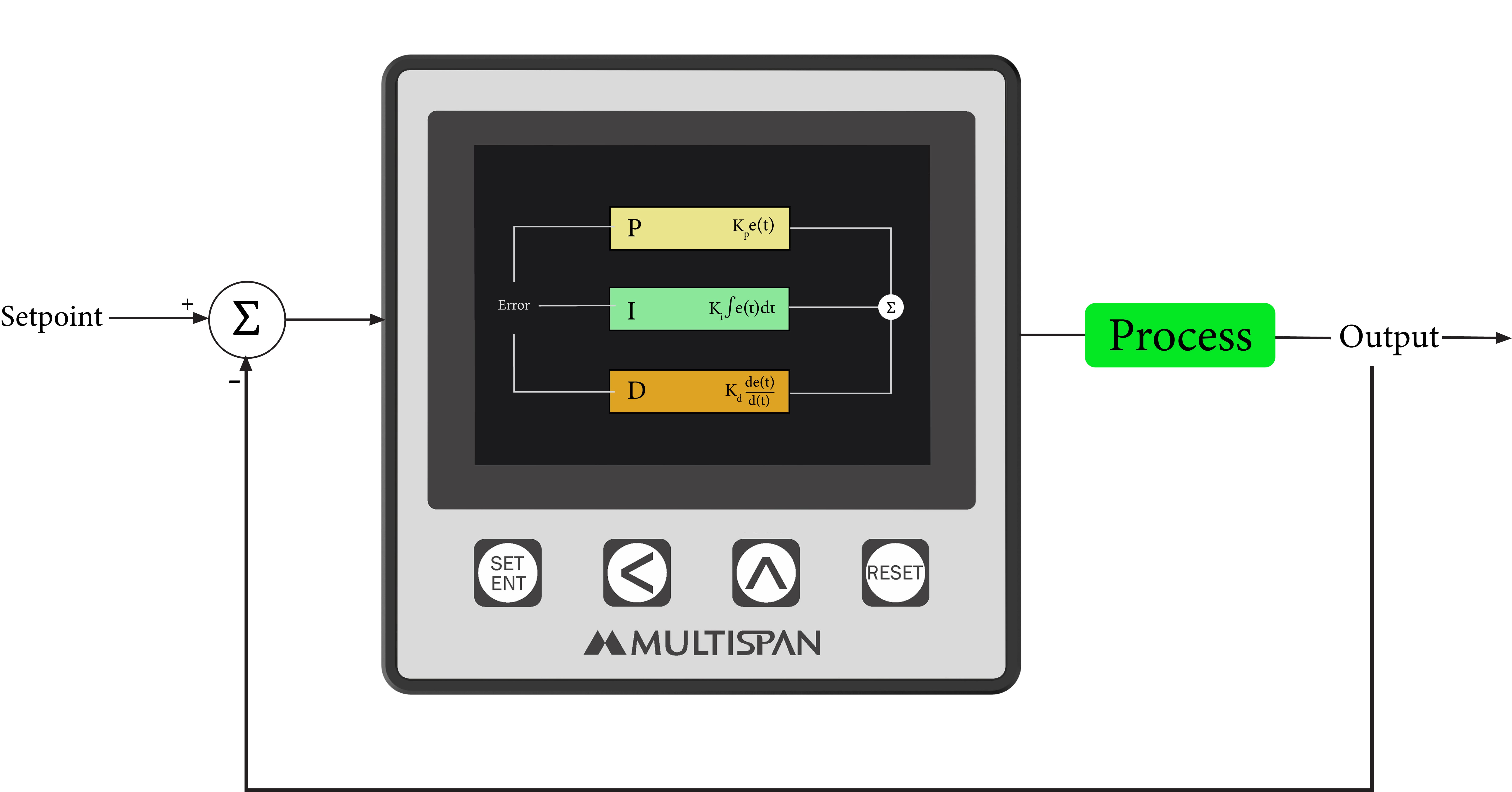
In the above block diagram, each part has been shown properly:
- Reference or Setpoint
- Proportional Action (P)
- Integral Action (I)
- Derivative Action (D)
- Plant Operation or Structure
- Actual Response or Output
- Feedback Path
- Summing Points
The function of a PID controller
The PID controller serves the purpose of providing feedback to match a setpoint. For example, forcing a thermostat to turn on or off based on preset temperature. PID controllers are best used in systems which have relatively small mass and those that display quick reactions to changes in energy added in the process. It automatically compensates the amount of energy available or the mass to be controlled due to frequent changes in setpoint and is hence recommended in systems where the load changes often.
How does the PID controller work?
The PID controller works in a closed-loop system, maintaining output such that there is zero error between the process variable and setpoint/desired output.
Closed-loop system: a brief overview
To understand the working of the PID controller adequately, let’s first discuss how the closed-loop system works. The output of a PID controller is equal to the control input to the plant. It is calculated from the feedback error. The following equation describes the calculation in the time domain:
u(t) = Kp*e(t) + Ki*e(t)*dt + Kp*dedt
Here, e(t) is the tracking error, i.e. the difference between the desired output (r) and the actual output (y). The actions taken by the PID controller broadly depend on this value. On receiving this value, the controller computes both the derivative and the integral of this error with respect to time. The control signal (u) is fed to the plant and the new output (y) is obtained. This new output (y) is then fed back and compared to the reference to find the new error signal (e).
The controller takes this new error signal and computes an updated control input. This procedure continues indefinitely. The transfer function of a PID controller is found by taking the Laplace transform:
Kp +Kis+Kd*s = Kd*s2 + Kp*s + Kis
The P, I, and D Terms
Let’s understand the proportional, integral and derivative terms (Kp, Ki and Kd).
The P term is represented by Kp and is the proportional gain. Upon increasing Kp, the control signal for the same level of error increases proportionally. Additionally, it’ll reduce (but not eliminate) the steady-state error.
The I term represents the integral term Ki. Upon the build-up of persistent steady error, increasing the value of I drives the error down. The downside to this is that it can make the system slow-moving and oscillatory since when the error signal changes sign, it may take a while for the integrator to adapt accordingly.
The D term is the derivative term of the controller (Kd). It allows the controller to anticipate error. As derivative control increases so does the error, that is, the signal can become large if the error begins to slope upward even if the magnitude of the error itself is relatively small.
P-Controller
Proportional or P-controller reduces the rise time, increases the overshoot and reduces the steady-state error. It gives an output that is proportional to the current error value e(t). It compares the desired or setpoint with the actual value or feedback process value. The resultant error is multiplied with a proportional constant to get the output. If the error is zero, the output is zero (however, this is practically never the case).
When used alone, the P-controller needs biasing or manual reset. This is because it never reaches the steady-state condition. While it provides stable operation, it always maintains some value of steady-state error, however minimal. The response speed is directly proportional to Kp.
I-Controller
As the P-controller is limited in its ability to eliminate steady-state error, there is an offset between the process variable and setpoint. This is where the I-controller comes in. It integrates the error over a period of time until the error value reaches zero and holds the value to the final control device at which the error becomes zero.
If the error values are negative, the integral control decreases accordingly. This simultaneously limits the response speed and the stability of the system. The response speed increases as Ki decreases. Hence, the PI controller is mostly used in cases where high-speed response is not critical.
D-controller
While the I-controller anticipates error, D-controller has the ability to predict the future behavior of error. Its output depends on the derivative of the error with respect to time, multiplied by the derivative constant Kd.
In the D-controller, the settling time of output is decreased. It also improves the stability of the system by compensating for phase lag caused by the I-controller. Derivative gain Kd is directly proportional to the response speed.
Tuning Methods
“Tuning” refers to the process of finding the range of values of the interacting parameters for which optimal performance can be achieved.
Depending on the process, different tuning settings are required to better suit the various facets of the situation the PID controller is being used in. For example, in a furnace, airflow will vary, the high temperatures will change fluid density and viscosity steadily and barometric pressure will vary over time. Hence, all of these need to be taken into account while selecting the PID settings (the gain applied to the correction factor called “reset” and the time used in the integral and derivative calculations called “rate”).
Manual Tuning
Manual tuning is done by setting the reset time to its maximum value and the rate to zero. Then the gain is gradually increased until the loop oscillates at a constant amplitude. Once this value is reached, the gain is set to half this value and the reset is adjusted so it corrects for any offset within an acceptable period. The biggest drawback is this process is too complex, challenging and involves a lot of calculations and effort.
Tuning Heuristics
First described by Ziegler and Nichols in 1942, their methods entail measuring the delay in response and the time taken to reach a new output value. Then the period of a steady-state oscillation is established. One of the issues with this method is it sometimes produces a response considered too aggressive in terms of overshoot and oscillation. It can also be time-consuming.
Automated Tuning
To overcome the disadvantages of the previous two methods, auto-tuning is preferred. All of Multispan’s PID controllers come equipped with auto-tuning. Basically, the PID controller “learns” to calculate the appropriate PID settings. It can respond to a disturbance or change in set point by observing both the delay and the rate with which the change is made. This allows us to deal with imprecision and nonlinearity in complex control situations.
Types of PID Controllers
Depending upon the system to be controlled, controllers can be divided into three basic types:
On/Off Controller

An on/off PID controller is the most fundamental form of the temperature control device. It gives a binary output of on or off with no middle state. This output changes only when the temperature crosses the setpoint. A particular example of on/off control is the limit controller. It is used to terminate a process when a preset value of temperature is exceeded.
Proportional Controller
The proportional control was designed to remove the cycling associated with on/off control. As the temperature approaches the setpoint, it decreases the average power supplied to the heater. This ultimately slows down the heater so that it will not surpass the setpoint but will approach the setpoint and maintain a stable temperature. This proportioning action can be accomplished by turning the output on and off for short time intervals. This "time proportioning" varies the ratio of "on" time to "off" time to control the temperature.

Standard PID Controller
This kind of PID controller will merge proportional control through integral & derivative control to automatically assist the unit to compensate modifications within the system. These modifications, integral & derivative are expressed in time-based units. The terms of PID must be adjusted separately otherwise tuned to a specific system with the trial as well as error. These controllers are also referred to through their reciprocals, RATE & RESET correspondingly. These controllers will offer the most precise and steady control of the three types of controllers.

Applications of PID Controller
PID controllers universally benefit almost every process control application. Hence, they can be seen in use in a variety of industries and fields. The best PID controller application, however, has to be temperature control where the controller uses an input of a temperature sensor and its output can be allied to the element (fan, heater, furnace, etc.)
Metal Furnaces
During heat treatment of metals, like “Ramp and Soak” sequences, precise control is required to ensure desired metallurgical properties are achieved. As the metal in the furnace is usually massive, its temperature doesn’t change easily even when huge heat is applied. This feature results in a moderately stable PV signal & permits the Derivative period to efficiently correct for fault without extreme changes to either the FCE or the CO.
Drying solvents from painted surfaces
Drying or evaporating of solvents from freshly painted surfaces need to be carried out at specific temperatures. Too high temperature conditions may cause damage to substrates while too low conditions may result in product damage and poor finishing. The same goes for the curing of rubber or leather.
pH control
As certain processes need pH values to be precisely within a particular range, PID controllers can be used for that too. Its behaviour may change according to the current operating range. The dynamics of pH tend to be slow as the acidity increases.
Baking
Precise temperatures need to be maintained in commercial ovens to ensure the necessary catalysts take effect and the desired reactions are carried out successfully.
Automatic Machine Control
PID controllers play an important role in the automatic machine control system too. Common processes they are used in are production counting, cutting, etc.
Automobile Industry
PID controllers also see a great demand in the automobile industry and are widely used such as car speed measurement, automatic driving or self-driving, etc.
MPPT Charge controller
Depending on weather conditions, the current and operating voltage of photovoltaic cells will change constantly. So it is extremely significant to track the highest power point of an efficient photovoltaic system. PID controller is used in MPPT (Maximum Power Point Tracking) by giving fixed voltage and current points to the PID as inputs.
Power Electronics
PID controllers are mostly used in converters, an application of power electronics. In addition to that, they are also used in inverters, voltage stabilizers, etc.
Apart from this their application is widespread such as plastic processing & testing machines, scientific laboratory and testing equipment’s like BOD, COD, Incubator, sterilizer’s, etc.
Why should you invest in PID controllers?
Advantages
- P Controller stabilizes the gain but produces a constant steady-state error.
- I Controller reduces or eliminates the steady-state error.
- D Controller reduces the rate of change of error.
- PID controller provides a very high-efficiency steady-state output than normal on/off controllers.
- As the PID controller works in three modes, error minimizing and data validation are easily possible.
Disadvantages
- Some PID controlling systems are complex in design and expensive
- The only other disadvantage is the tuning methodology
While these are the disadvantages of PID controllers found generally in the market, Multispan, at all times, strives to deliver innovative, affordable and user-friendly products for various industrial applications. Having first introduced PID temperature controllers in 2003, Multispan is now a pioneer in PID-based technology with solutions perfected over the years.
We offer PID controllers in the basic economic range which have a single display and single relay output (TC-49, UTC-121P, UTC-221P, UTC-421P). We also provide dual display and dual output PID controllers which are relatively higher in cost. These come in varied sizes to accommodate your needs (UTC-121G, UTC-221G, UTC-421G, UTC-321P, UTC-1202G, UTC-2202G, UTC4202G, UTC-3202G). Lastly, we have PID controllers with three outputs (UTC-4203, UTC-3203). All of these have elegant LED displays and auto/self tuning.
The biggest advantage of our range of PID controllers is they come built-in with modifications to better serve the exact situation they work in. Take the example of the plastics industry, we have PID controllers with built-in Ampere indication, meaning there is no need for separate ampere meters.
Another highlight of our controllers is we have a wide range, to combat the disadvantage of PID controllers being too expensive. We have models that are economically viable as well as premium ones with additional features. With sophisticated yet minimalistic designs, affordable prices and auto/self tuning methodology, these controllers make for premier choices when deciding where to buy from.
Hope this article allows you to make an educated decision while picking the PID controllers for your field of application. Still feel like you’re stuck at some point? If you need clarification or help of any sort regarding how to choose PID controllers, our team would be happy to help! Feel free to reach out to us at marketing.multispanindia.com


Leave A Comment